
Starter Motor Wiring Diagram
Wire A Starter Solenoid With The Wiring Diagram: A Step-By-Step Guide. Leave a Comment / Car Starting System / By IQBAL KHAN / November 1, 2022 / 9 minutes of reading. The starter solenoid is a switch that is used to engage the starter motor in order to start the engine. The solenoid is usually located near the battery and is activated when the.
Motor Starter 8538 Wiring Diagram Collection
just an idea on how a starter motor is wired up and how to BENCH test itmy other channel shed FLOOR build: https://www.youtube.com/watch?v=93mD8slVAbM&t=8s m.
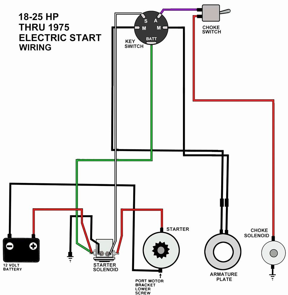
Briggs And Stratton Electric Start Wiring Diagram Wiring Diagram and
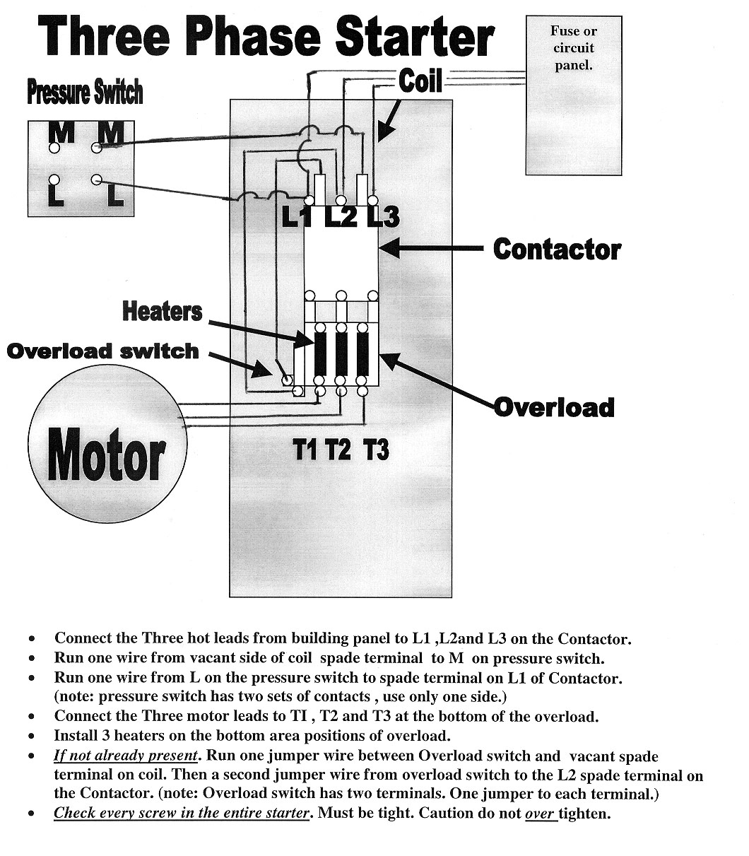
Three Phase DOL Starter Wiring Diagram: This is the basic wiring diagram of a DOL starter. Power Diagram: Control Diagram: MCCB or Circuit Breaker: The R, Y and B phase are connected through MCCB to the contactors. Magnetic Contactor: The contactor has 3 types of contacts:

Get Wiring Diagram Acg Starter Gif Wiring Diagram Gallery
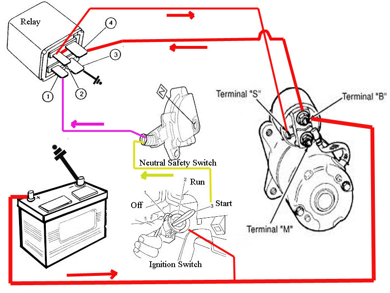
The Starter Motor Wiring Diagram. Remember, the starting motor uses two wiring circuits to complete its operation. The first one is the control circuit, and the second one is a heavy electric circuit. The control circuit turns ON and OFF the solenoid and is controlled by the ignition switch. It consumes less current, and these cables are thin.

Powermaster Starter Wiring Diagram
Starter Solenoid Wiring Diagram: 3 Pole Starter Diagram. A starter solenoid is an electromagnetic switch that produces a magnetic field to connect and disconnect the battery to the starter motor assembly. It is a huge switch, which works as a bigger relay to turn ON and OFF the starter motor assembly. The solenoid works on the principle of.

⭐ Chevy Truck Starter Wiring Diagram ⭐ The tasteless
Siemens Motor Starter Wiring Diagram (A Complete Guide) by Charles Clark November 7, 2023. Siemens motor starters are essential for controlling the operation of electric motors. They ensure that motors start, stop, and run smoothly, protecting both the equipment and the personnel involved. Understanding how to wire them is crucial for various.
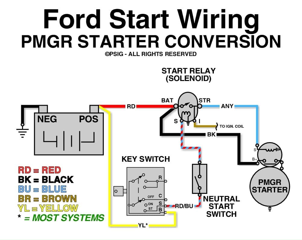
Ford Starter Relay Wiring Diagram Pictures
Starting System & Wiring DiagramAmazon Printed Bookshttps://www.createspace.com/3623931Amazon Kindle Editionhttp://www.amazon.com/Automotive-Electronic-Diagn.
Starter Wiring Diagram Wiring Diagram
Although the star delta starter wiring diagram is very helpful and easy to read. It isn't quite correct. On the delta contactor side you have W2,V2,U2 going to the motor.. and detail drg. waitig in the future every electrical drawings/diagrams to get in my e-mail address. especially I need wiring ckt diagram of an ATS systems generator to.
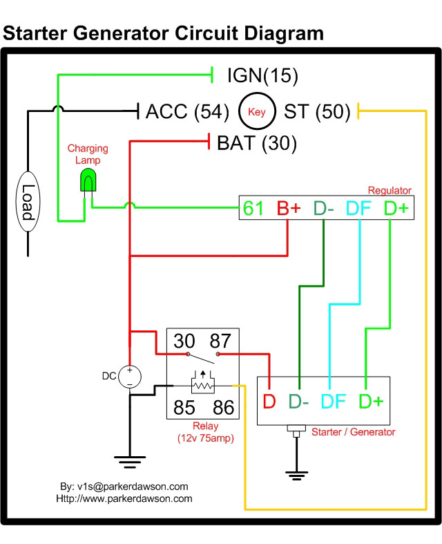
Delco Starter Generator Wiring Diagram Bestn
In this video I show how to wire a starter relay, starter solenoid, and neutral safety switch on an engine. I also explain how to bypass the solenoid if need.
Circuit Diagram Of Starter Motor
The Simple Chevy 350 Starter Wiring diagram is a diagram that illustrates the wiring stem of a Chevy 350 Starter. This diagram illustrates the precise connections and components involved in the starter circuit, making it easier to comprehend the flow of electricity and the functionality of the starting system. It does not only guide you when.
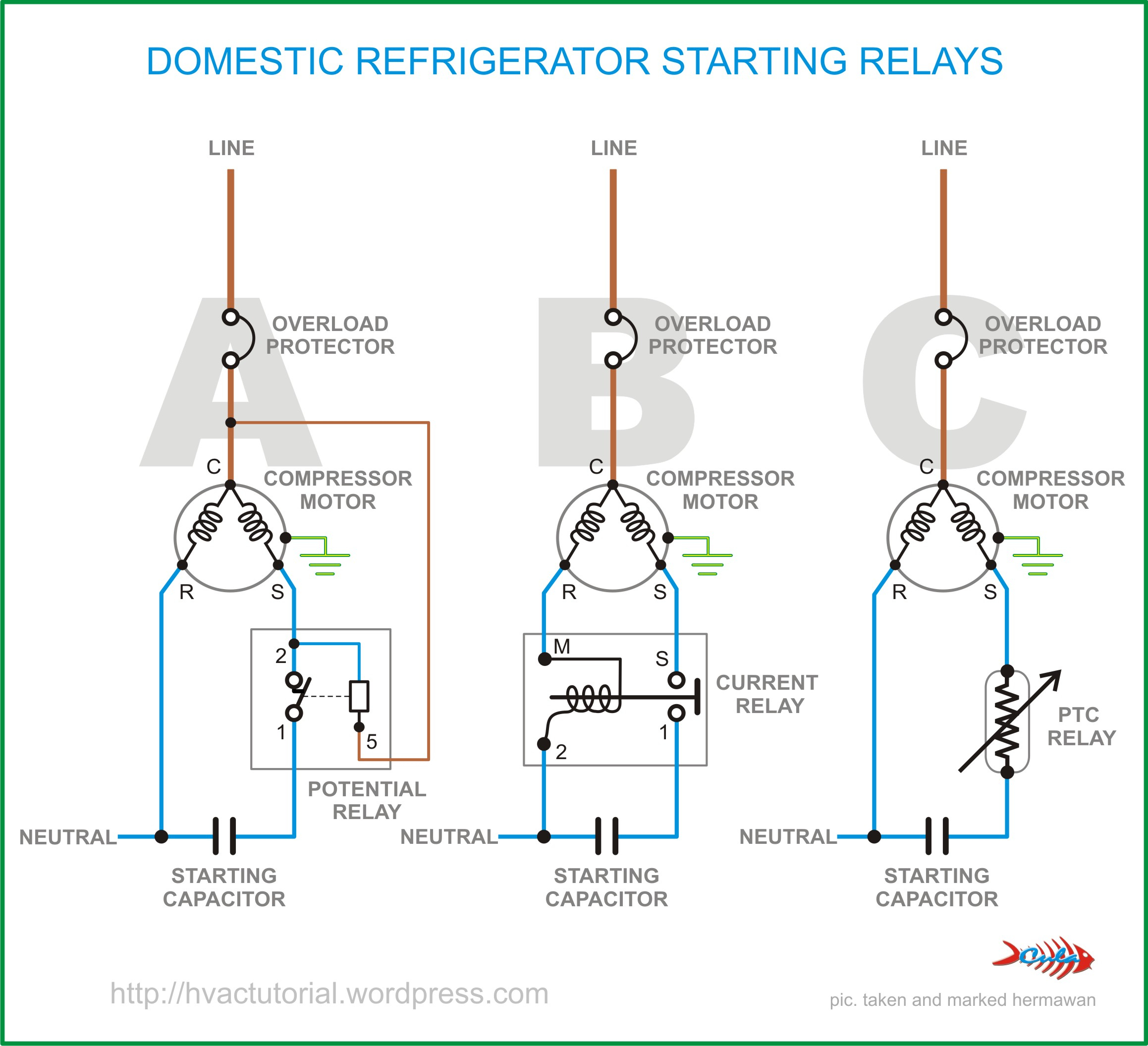
Refrigerator Start Relay Wiring Diagram Cadician's Blog
Learn how your vehicle's starter motor and ignition system circuit work, including how the ignition switch, relay and safety gearshift are wired to kick star.

Square D Combination Starter Wiring Diagram Free Wiring Diagram
GM starter wiring diagram. If you have a late model GM vehicle and turn the key only to hear nothing, you'll most likely think you have a dead battery—and you may. But a no start, no crank, no click condition can be far more involved than that. In the old days, power flowed through the ignition switch and down to the starter solenoid.

4 Pole Starter Solenoid Wiring Diagram Printable Form, Templates and
There are four basic wiring combinations: a) Full-voltage non-reversing 3-phase motors. b) Full-voltage reversing 3-phase motors. c) Single-phase motors. d) Wye-delta open transition 3-phase motors. You must supply a disconnect switch, proper sized wire, enclosures, terminal blocks and any other devices needed to complete your circuit.

Remote Car Starter Wiring Diagrams
The power and control circuits of a star-delta starter are discussed in this article with the help of an actual star-delta starter wiring diagram. You can find the instructions to calculate the ratings of contactors for a star-delta starter circuit here: Star-Delta starter design tool.
honda gx390 ignition wiring diagram
Standard duty "START-STOP" stations are provided with the connections "A". shown in the adjacent diagram. This. connection must be removed from all but one of the "START-STOP" stations used. Heavy duty and oiltight push button stations can also be used but they do not. have the wiring connection "A", so it must.

Triaging a nocrank condition and testing a starter motor Hagerty Media
If you don't see what you're looking for, please ask. Springer Controls has a certified UL508A panel shop to build custom starters and control panels up to 500V. For any custom options like HOA (Hand-Off-Auto) starters, pilot lights, control transformers, or volume purchases, please contact us at 888-357-2138.
